The following is a method you can use to determine the number of packets per second crossing an interface. The example interface used is eth-s1p1: nokia[admin]# netstat –i | grep eth-s1p1; sleep 10; netstat –i | grep eth-s1p1 Name Mtu Network Address Ipkts Ierrs Opkts Oerrs Coll eth-s1p1 9600 0:a0:8e:70:fd:48 3254126830 0 1488520554 eth-s1p1 9600 0:a0:8e:70:fd:48 3254399730 0 1488822824 What the preceding command does is output two lines: the number of packets the interface has seen when the command is first executed, and the number of packets seen 10 seconds later. Given that information, we can deduce the number of packets per second, both coming into and going out of the box. As you see there are 2 columns for each interface after the MAC address. The first column input packets, the second is out packets. To figure out total: ((3254399730–3254126830)/10)+((1488822824–1488520554)/10) = 57517 packets Here is how you find packets per second and bytes per second nokia[admin]# netstat -ib | grep eth-s1p1; sleep 10; netstat -ib | grep eth-s1p1 Name Mtu Network Address Ipkts Ierrs Ibytes Opkts Oerrs Obytes Coll eth-s1p1 9600 0:a0:8e:70:fd:48 3286824714 0 3134996150 1524566033 0 703331799 0 eth-s1p1 9600 0:a0:8e:70:fd:48 3287099394 0 3335905031 1524872800 0 867944108 0 Packets per second – to find total add both Ipkts and Opkts ((3287099394-3286824714)/10)+((1524872800-1524566033)/10)= 58144 Bytes per second - to find total add both Ibytes and Obytes ((3335905031-3134996150)/10)+((867944108-703331799)/10)= 36552118 bytes To get your average packet size divide bytes by packets |
Thursday, April 26, 2012
Packets per second crossing an interface?
Monday, April 23, 2012
Upgrading Provider-1
Download the R75 .iso
Copy it to the /var directory
Verify the md5 checksum
Mount the .iso image in the local /var using:
mount -t iso9660 -o loop (location of .iso image/name of file) /mnt/cdrom
In my case I put the .iso in the /var/R75 directory:
mount -t iso9660 -o loop /var/R75/Check_Point_R75_MD.Splat.iso /mnt/cdrom
Now run the mds_setup script from:
/mnt/cdrom/linux/p1_install/mds_setup
Follow the upgrade process, and (usually) accept all of the defaults.
Reboot
When your MDS wakes up, it will be an MDM.
mdsstat
Tuesday, April 3, 2012
Understanding VRRP flapping by member state
- A normal HA failover within IPSO will begin with member A in MASTER state, and member B in BACKUP. As an outage, or some problem, occurs on member A one of the following (depending on configuration of interfaces in VRRP) will take place:
- a. If member A powers down, panics or reboots, VRRP HELLO packets will stop being sent to member B. At which point, once the set number of packets is missed on member B it will consider itself the higher priority and become MASTER.
- b. If an interface participating in the VRID group fails, or Firewall State Monitoring detects a critical device as failing, the IPSRD (IPSO routing daemon) will lower the priority of all interfaces within the associated VRID group or all VRID groups, respectively. These lower priority updates will be sent to member B, and the associated interfaces will place themselves in MASTER state.
- With VRRP, there are a few common scenarios where cluster members change from the standard Master / Backup state. In most cases, the status of the members during the problem period can assist in determining the cause of the issue
MASTER/MASTER
One concerning situation is when both members, or the associated member interfaces, consider themselves in MASTER state at the same time. This may be seen in brief instances, or a constant occurrence. In either case, it is easiest to troubleshoot the situation once you understand the following:
Interfaces participating in a VRRP cluster will enter a MASTER/MASTER situation when each member believes it was the highest priority. In this case neither members associated interface will be in BACKUP. Common reasons for such a situation include:
- When neither interface is receiving HELLO packets from the other member due to congestion or failure on the line between them
- When issues with ADP, congestion or buffering issues on the interface prevent HELLO packets from being processed by the target member
BACKUP/BACKUP
Another more concerning situation is when both members consider themselves in BACKUP state. BACKUP state means that neither member is advertising the Virtual IP and no traffic is being processed by the cluster. Once again, this may be a brief flapping, or an ongoing issue. BACKUP/BACKUP is generally rare, but should be understood by the following in order to troubleshoot:
A member, or interface, will place itself in BACKUP state when either it has received HELLO packets with a priority value higher to that of its own OR it will place all its own interfaces into BACKUP state and reduce its priority when Firewall State Monitoring deems critical devices in a problem state, enough that the member is not fit to participate as the MASTER. As it is uncommon for both members to be receiving lower priority packets to their own simultaneously, it is the later of the above situations which of greater concern.
| Firewall State Monitoring (see sk39008 for a detailed description of this function) BACKUP/BACKUP flapping with Firewall State Monitoring usually occurs when member A in MASTER state is under heavy load processing traffic and fails to successfully monitor its own key firewall/clustering processes. In this case member A reduces its priority and places itself in a BACKUP state. The lowered priority is then sent to member B which places itself in MASTER. At this point, because the same traffic is sent to the new MASTER, member B fails to monitor its own key processes and places itself in BACKUP. The cycle continues due to the specific load and the members flap between BACKUP > MASTER > BACKUP until the load is reduced. BACKUP/BACKUP constant situation is a twist on the above, whereby a specific issue has killed one or more of the critical devices on the MASTER, and the same has then happened on the new MASTER. This situation is most likely more problematic and should be investigated further to determine the actual cause of the failure. |
| SOLUTION |
| MASTER/MASTER Troubleshooting a Master/Master scenario requires investigation into where the HELLO packets being delayed or dropped along the line between associated member interfaces. Remember, if there is an issue with the directly connected upstream ports, the local interfaces would consider themselves to be DOWN and this would have an entirely different VRRP effect. In some cases the issue has been found to be latency caused by processing of HELLO packets through an external IPS solution between members. A well ordered TS process would include:
This situation is considered avoidable. One way is by increasing the interval in which the critical processes report their status as per sk39008. Alternatively, this can be achieved by enabling Firewall State Monitoring only on the current MASTER (if this member is to be kept as the primary MASTER), and disabling it on the BACKUP. In this case, the heavy traffic load or traffic patterns will not cause the new MASTER to failover aswell. The fact that the initial MASTER failed over will provide a means to investigate, avoiding future occurances. Source: Checkpoint site |
Monday, April 2, 2012
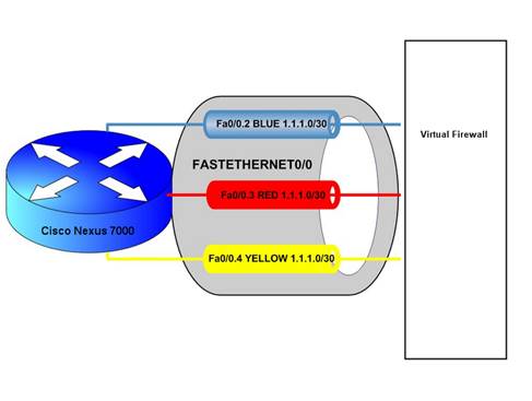
VRF: Virtual Routing and Forwarding
Virtual Routing and Forwarding is commonly used by Service Providers to provide services within an MPLS cloud with multiple customers. The most interesting feature of this is that, VRF allows creation of multiple routing tables within a single router. This means that overlapping use of IP addresses from different customers is possible. Some enterprises use VRF to seggrate their services like VOIP, wireless, geographical location and other varieties.
Subscribe to:
Posts (Atom)